The role and functions of Ground Fault Protection
 This type of protection is defined by the NEC (National Electrical Code) to ensure protection against fire on electrical power installations.
To ensure protection against fire:
- The NEC defines the use of an RCD with very low sensitivity called GFP
- IEC 60 364 standard uses the characteristics of the TT system combined with low or high sensitivity RCDs.
These protections use the same principle. Fault current measurement using:
- A sensor that is sensitive to earth fault or residual current (earth fault current)
- A measuring relay that compares the current to the setting threshold
- An actuator that sends a tripping order to the breaking unit on the monitored circuit in case the threshold setting has been exceeded.
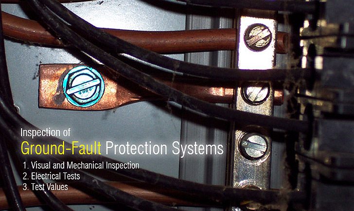
1. Visual and Mechanical Inspection
- Compare equipment nameplate datawith drawings and specifications.
- Inspect the components for damage and errors in polarity or conductor routing:
- Verify that ground connection is made ahead of the neutral disconnect link and on the line side of any ground fault sensor.
- Verify that the neutral sensors are connected with correct polarity on both primary and secondary.
- Verify that all phase conductors and the neutral pass through the sensor in the same direction for zero sequence systems.
- Verify that grounding conductors do not pass through the zero sequence sensors.
- Verify that the grounded conductor is solidly grounded.
- Inspect bolted electrical connections for high resistance using one of the following methods:
- Use of low-resistance ohmmeter in accordance with Section 7.14.2.
- Verify tightness of accessible bolted electrical connections by calibrated torque-wrench method in accordance with manufacturer’s published data or Table 100.12.
- Perform thermographic survey in accordance with Section 9.
- Verify correct operation of all functions of the self-test panel.
- Verify that the control power transformer has adequate capacity for the system.
- Set pickup and time-delay settings in accordance with the settings provided in the owner’s specifications. Record appropriate operation and test sequences as required by NFPA 70 National Electrical CodeArticle 230.95.
* Optional
2. Electrical Tests
- Perform resistance measurements through bolted connections with a low-resistance ohmmeter, if applicable, in accordance with Section 7.14.1.
- Measure the system neutral-to-ground insulation resistance with the neutral disconnect link temporarily removed. Replace neutral disconnect link after testing.
- Perform insulation resistance test on all control wiring with respect to ground. Applied potential shall be 500 volts dc for 300 volt rated cable and 1000 volts dc for 600 volt rated cable. Test duration shall be one minute. For units with solid-statecomponents or control devices that can not tolerate the applied voltage, follow manufacturer’s recommendation.
- Perform the following pickup tests using primary injection:
- Verify that the relay does not operateat 90 percent of the pickup setting.
- Verify pickup is less than 125 percent of setting or 1200 amperes, whichever is smaller.
- For summation type systems utilizing phase and neutral current transformers, verify correct polarities by applying current to each phase-neutral current transformer pair.
This test also applies to molded-case breakers utilizing anexternal neutral current transformer.- Relay should operate when current direction is the same relative to polarity marks in the two current transformers.
- Relay should not operate when current direction is opposite relative to polarity marks in the two current transformers.
- Measure time delay of the relay at 150% or greater of pickup.
- Verify reduced control voltage tripping capability is 55 percent for ac systems and 80 percent for dc systems.
- Verify blocking capability of zone interlock systems.
* Optional
3. Test Values
- Compare bolted connection resistances to values of similar connections.
- Bolt-torque levels should be in accordance with Table 100.12 unless otherwise specified by manufacturer.
- Microhm or millivolt drop values shall not exceed the high levels of the normal range as indicated in the manufacturer’s published data. If manufacturer’s datais not available, investigate any values which deviate from similar connections by more than 50% of the lowest value.
- System neutral-to-ground insulation shall be a minimum of 1.0 megohm.
- Insulation-resistance values for control wiring shall be a minimum of 2.0 megohms.
- Relay timing shall be in accordance with manufacturer’s specifications but must be no longer than one second at 3000 amperes.
Fuente de la noticia: electrical-engineering-portal.com


